Overview
Heat set inserts are threaded metal components that can be embedded into 3D printed parts to create durable, reusable threads for screws. They are commonly used in applications where repeated assembly and disassembly are required, as they provide better wear resistance than threading directly into plastic. Heat set inserts are particularly useful for parts made from materials like PLA or ABS, which may not hold up well to repeated threading. They are widely used in functional prototypes, electronics enclosures, and mechanical assemblies where strong, reliable fastenings are needed. In this module you will learn how to design a part to be used with heat set inserts as well as installing the inserts into the part.
Part Drawings for Heat Set Inserts Available in ME 2109
Overview
Heat set inserts are a wonderful tool to have as they can add significant functionality to a part.
Before you start using heat set inserts, you have to be figure out as well as be mindful of a couple of things.
- Insert Size and Type: You have to choose the insert size that you want as well as find the dimensions of this part. Choose an insert that will allow you get the desired functionality out of the part, without compromising the structural integrity of the part. Also ensure that the dimensions of the insert fit within the part.
- Hole Design: After you have chosen your insert, and found the dimensions, you have to design the hole to be slightly smaller than the outer diameter of the insert. You also have to make sure that the hole is deep enough so that the end of the bolt will not bottom out.
- Wall Thickness: There needs to be enough material around the insert location so that the insert is able to withstand the forces during use. Additionally, there needs to be enough perimeter walls around the hole to have a good fit.
- Location: Be mindful of the location of the insert and make sure to give yourself enough clearance for the install tool. (If the install tool will not work, talk to a TA about other ways to install heat set inserts). Also, the insert location needs to be perpendicular to the face. This helps ensure even pressure during the install, meaning that the screw interfacing with the part will be straight.
Overview
The part design is where all of the set up occurs for the use of heat set inserts. In order to have success, you have to pre-design the hole for the insert and make sure that it has the proper dimensions.
Using a Part Drawing
Once you have decided what size insert you want to use, open up the part drawing for that particular insert. The two most important dimensions are the larger outer diameter, as well as the length of the insert. When you are designing your part, you need to have an interference fit of around 0.2-0.4 mm with the outer diameter of the insert. The larger the interference, the better the fit (usually), but this also usually leads to a build up of material around the insert, which can look unprofessional. The other dimension you need to be mindful of is the length of the insert. If you set the hole depth is less than the insert length, the insert will protrude out of the part. More importantly, you need to make sure that the hole is deep enough so that your fastener will not bottom out on the plastic.
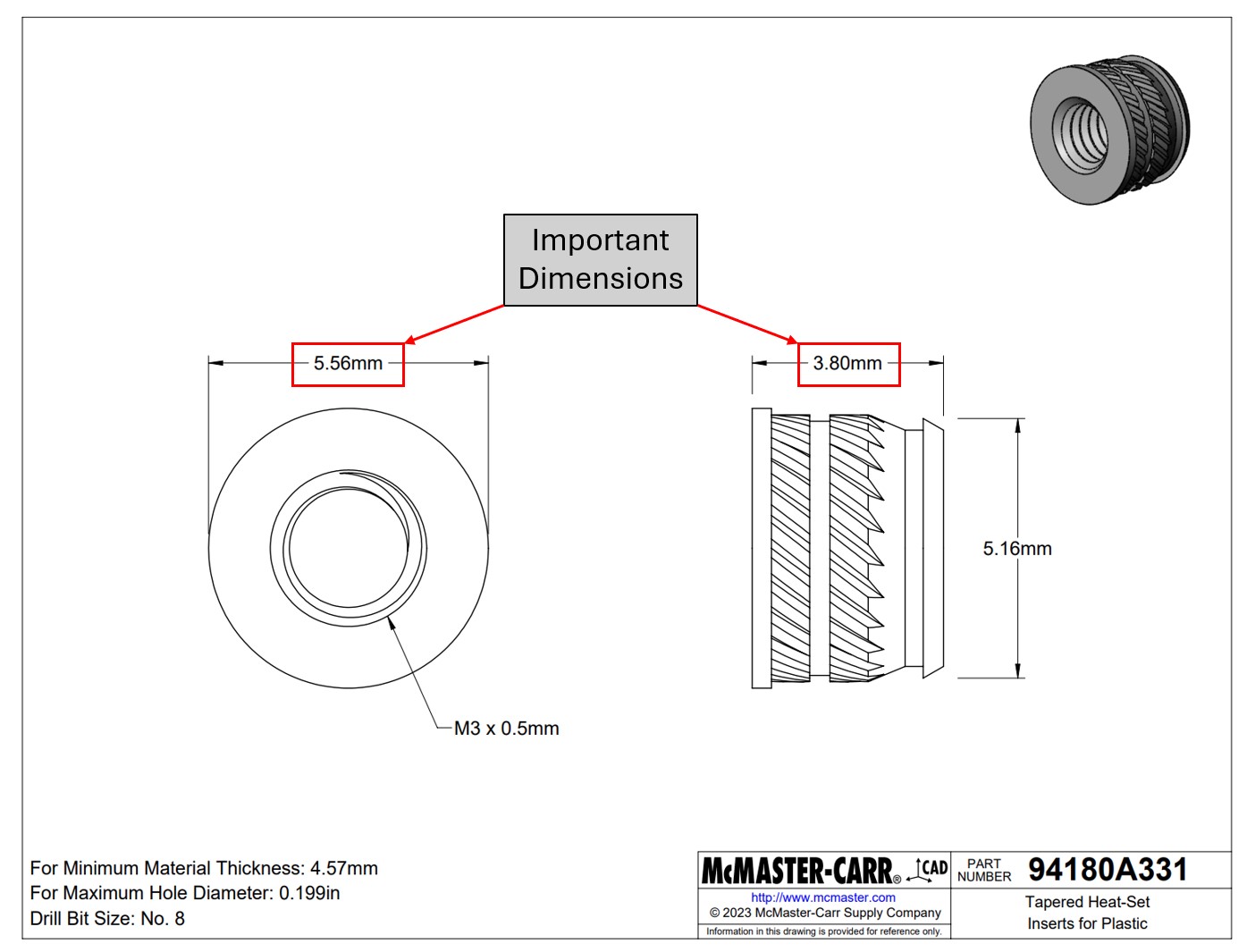
Figure 1. M3 Heat Set Insert Drawing with the important dimensions highlighted.
Modeling
Once you have the important dimensions, take to your preferred modeling software, and model your insert holes. Again, be mindful of the location of the inserts and make sure that there is enough material around the insert.
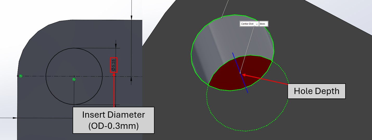
Figure 2. The insert hole modeled in SolidWorks. Note that the hole diameter is the outer diameter of insert minus 0.3mm, and the hole depth is deeper than the insert length.
Overview
Before you print your part, there is a couple of things that are recommended to do within the slicer to improve the quality of the insert. These setting changes are for the infill as well as the wall loops. Turning up the infill a little bit will improve your parts strength, and adding additional wall loops will improve the bond between the plastic and inserts.
Recommended Settings
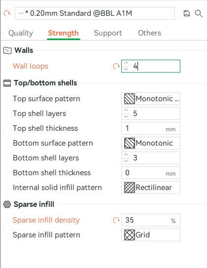
Figure 1. Use these settings as a starting point for using heat set inserts, and tweak them as you need for your application.
Infill
It is recommended that when using inserts, the part has an infill percentage of 25% or more, depending on the use case. If it needs to be strong, do not be afraid to really turn up that infill percentage.
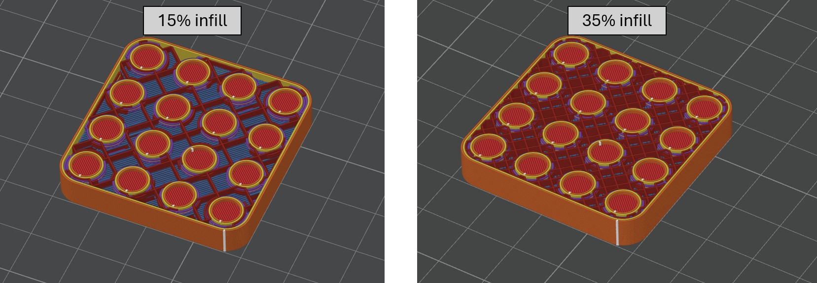
Figure 1. 15% infill versus 35% infill.
Wall Loops
The other recommended setting is increasing the amount of wall loops. This is important as it increases the amount of plastic that the insert can grab into, increasing the bond strength.
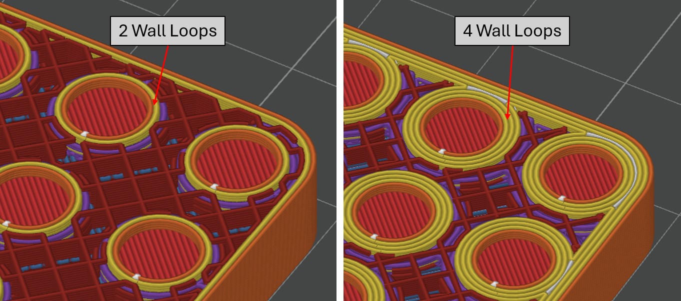
Figure 3. 2 wall loops versus 4 wall loops. Notice how 4 wall loops has significantly more plastic for the insert to “bite” into.
Overview
Installing inserts is a fairly simple task, but it is important to do a couple things in order to have success. The install process includes heating the insert with a specialized soldering iron, then pressing it into the designed insert location. Be careful of the soldering iron as it is VERY hot!
Insert Press
We have a small heat press insert device that can help you press the inserts in. The press is pictured below.
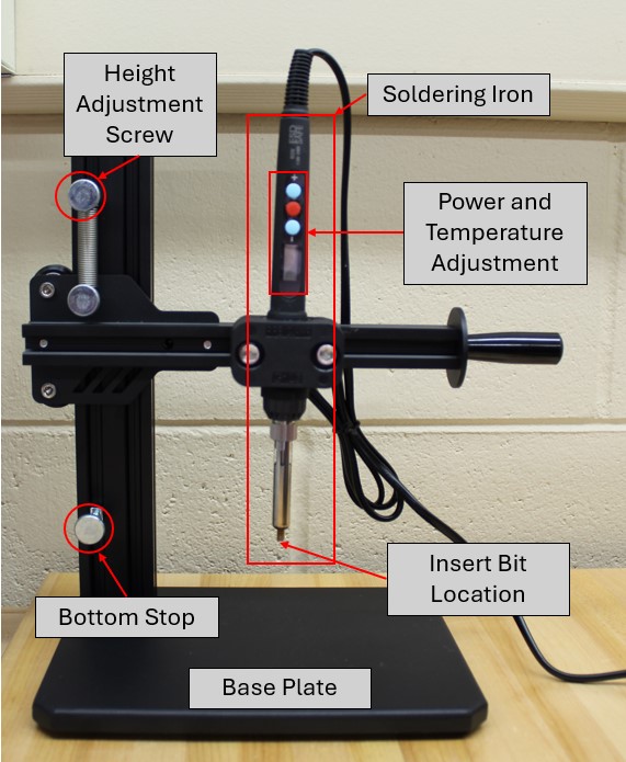
Figure 1. Heat Press Device
If your part does not interface with this machine, talk to one of the TAs for alternative ways to install heat set inserts.
Device Setup
Before plugging in the machine, find your insert bit in the small red box for your inserts and screw it onto the soldering iron. After this adjust the soldering iron height with the screws on the vertical extrusion so that your part has proper clearance under the press.
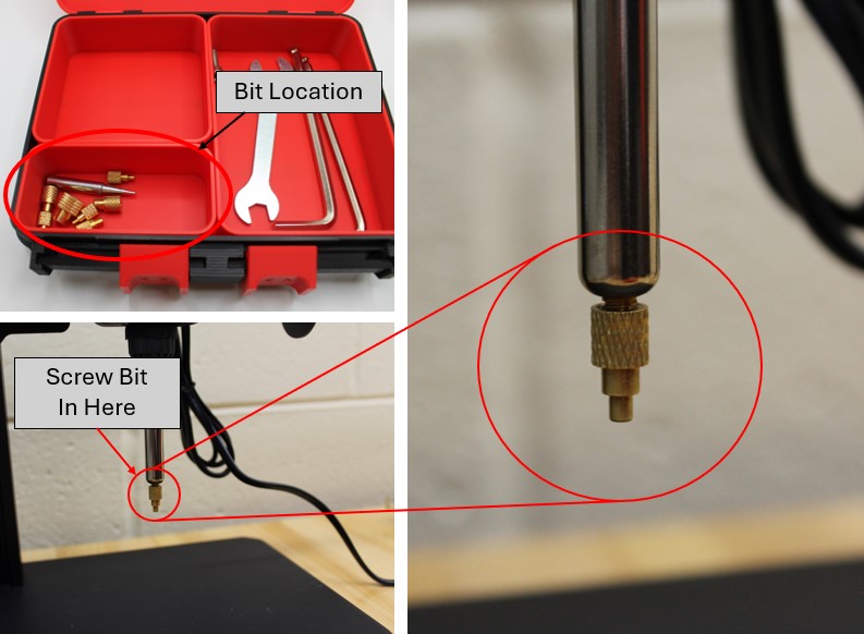
Figure 2. Installing heat press bit onto soldering iron.
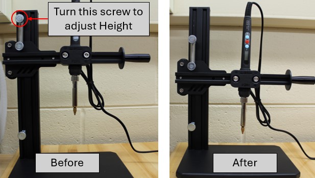
Figure 3. Adjusting the height of the press.
To turn on the soldering iron, hold the red button in the middle for ~5 seconds, until the screen turns on. Using the +/- buttons on the soldering iron, set the temperature to be around 20 degrees hotter than the printing temperature of the material. For example, PLA prints at 200-220 C, so set the iron to be at 240-260 C.
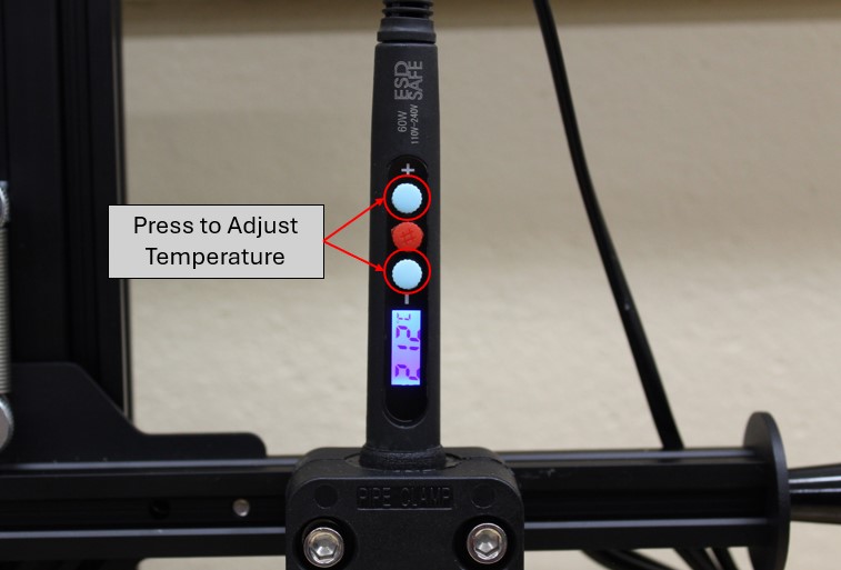
Figure 4. Adjusting the temperature on the soldering iron.
Install
Once the machine is set up, place your part with the insert resting on top of the designed hole, under the press.
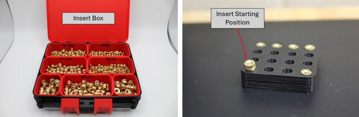
Figure 5. Heat set insert box (left) and the starting position for install(right).
Line the insert up with the iron, and press into the insert so that the insert is on the tool. Allow a couple of seconds for the insert to heat up, then gently press the insert into the design hole. Once it is flush with the top, lift the press off of the insert, and allow 15-30 seconds for the insert to cool.
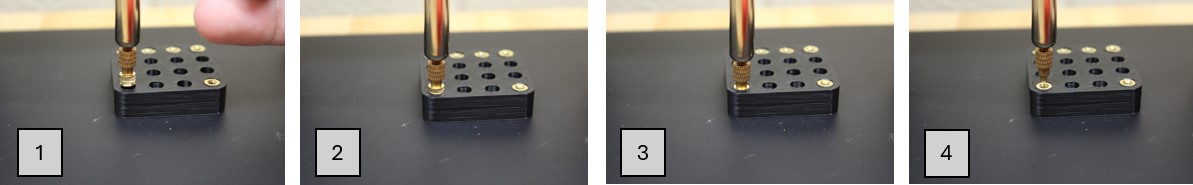
Figure 6. Pressing the insert into the part.
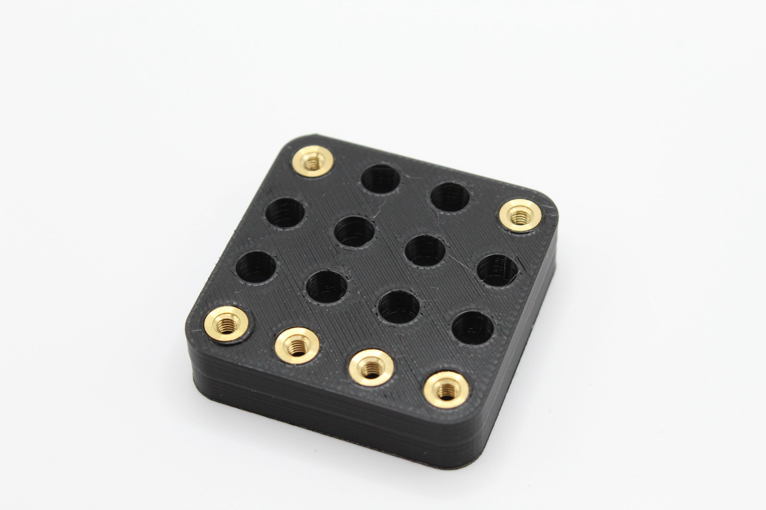
Figure 7. Successfully installed heat set inserts.